The power source is 18 for my fp but the MCU and Input Sensor can only tolerate 5V so the REGULATOR must be used to reduce the voltage - Your Heat Pads needs 18V...so it CANNOT be connected directly to your MCU (which can only output 5V). A 'Middle Man' device (a SWITCH) needs to be put in between your Pads and your MCU. Your MCU will send a 5V signal to this SWITCH to turn it ON (allow 18V to flow through the SWITCH) or turn it OFF (block 18V from flowing through the SWITCH). In this case, a voltage regulator should be used to reduce the voltage from 18V to 5V for the MCU and input sensor. Additionally, a switch or relay should be used as a "middle man" device to control the flow of power to the heating pad. The MCU can send a 5V signal to the switch or relay to turn it on and allow 18V to flow through the switch and power the heating pad. It is important to ensure that the switch or relay can handle the voltage and current requirements of the heating pad.
When using a voltage regulator to drop the voltage from 18V to 5V, heat will be generated due to the energy lost in the regulator. To handle this, a heat sink can be added to the regulator to dissipate the heat. Additionally, the regulator should be chosen based on its maximum power dissipation and thermal resistance specifications to ensure that it can handle the power requirements of the heating pad and dissipate the heat generated without overheating.
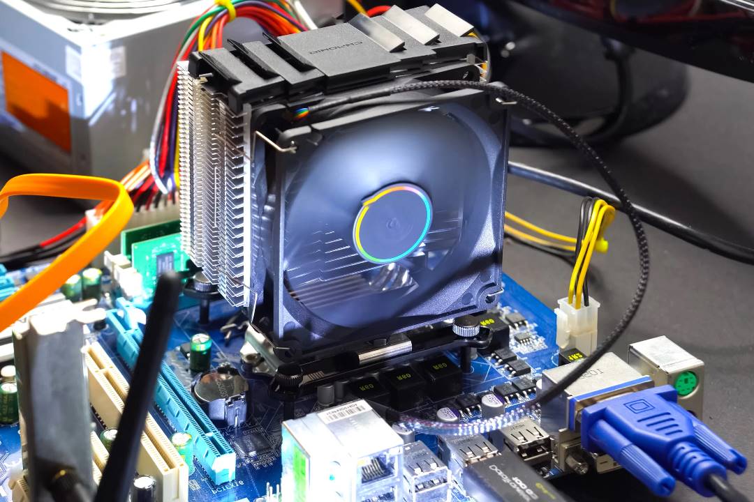
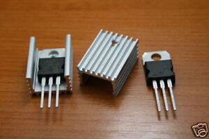
A heat sink is a device that helps to dissipate heat away from a hot object, such as a CPU or other electronic component, in order to prevent it from overheating and malfunctioning. It works by increasing the surface area of the object, allowing more heat to be transferred away from it and into the surrounding environment. Heat sinks are commonly made of materials such as aluminum or copper, and are often designed with fins or other features to increase their effectiveness.
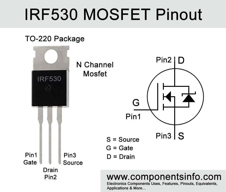
A MOSFET is a type of transistor that can be used as a switch in electronic circuits. It can handle high currents and voltages and is commonly used to control the flow of power to loads such as motors, lights, and heaters. In this project, a MOSFET is used as a switch to control the flow of power to the heating pad. The MOSFET is turned on and off by a 5V signal from the MCU, which allows or blocks the flow of power to the heating pad. It is important to choose a MOSFET that can handle the voltage and current requirements of the heating pad. Some MOSFETs that can be used for heating pads include the IRF540N, IRFZ44N, and FQP30N06L.
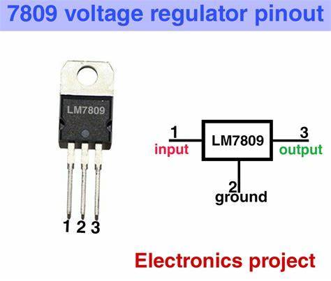
For my project i am using a voltage regulator that can handle the voltage and current requirements of my MCU and other components. A popular voltage regulator is the LM7805, which can regulate up to 35V input voltage down to a stable 5V output voltage. The LM7805 can handle up to 1A of current, which should be sufficient for your MCU and other components. For the MOSFET, you can use a MOSFET that can handle the voltage and current requirements of your heating pads. As I mentioned earlier, some MOSFETs that can be used for heating pads include the IRF540N, IRFZ44N, and FQP30N06L. These MOSFETs can handle up to 60V and 30A, which should be sufficient for the 18V power supply and nichrome wire heating pads. When choosing a MOSFET, you should also consider its gate threshold voltage (Vgs) and on-resistance (Rds(on)). The gate threshold voltage is the voltage required to turn on the MOSFET, and the on-resistance is the resistance of the MOSFET when it is turned on. You should choose a MOSFET with a gate threshold voltage that is compatible with your MCU output voltage and an on-resistance that is low enough to minimize power loss and heat generation. Once you have chosen a voltage regulator and MOSFET, you can connect them to your circuit according to the circuit diagram for your project. The voltage regulator will regulate the voltage from your battery down to a stable 5V for your MCU and other components, while the MOSFET will act as a switch to control the power to your heating pads.So in the lab there was only IRF530 mosfet instead of IRF540N but there was any big difference since The IRF530 MOSFET and LM7809 voltage regulator can be appropriate for a heating jacket project because they have specific features that make them well-suited for this application. The IRF530 MOSFET is a power MOSFET that can handle high currents and voltages. It has a low on-resistance, which means that it can switch high currents with low power dissipation. This makes it a good choice for controlling a heating element in a jacket, as it can handle the high current required to heat the element. The LM7809 voltage regulator is a linear voltage regulator that can provide a stable 9V output voltage from a higher input voltage. It has a low dropout voltage, which means that it can still operate with a small difference between the input and output voltages. This makes it a good choice for powering the MCU and other components in your jacket, as it can provide a stable voltage even if the input voltage varies. Overall, the IRF530 MOSFET and LM7809 voltage regulator can be a good choice for a heating jacket project because they have the necessary features to handle the high currents and voltages required to heat the jacket, as well as provide a stable voltage to power the other components.
Yes, you can use IRF530N MOSFET instead of IRF540N MOSFET as both are N-channel MOSFETs with similar specifications. However, IRF530N MOSFET has a lower maximum current rating and a higher gate threshold voltage compared to IRF540N MOSFET.
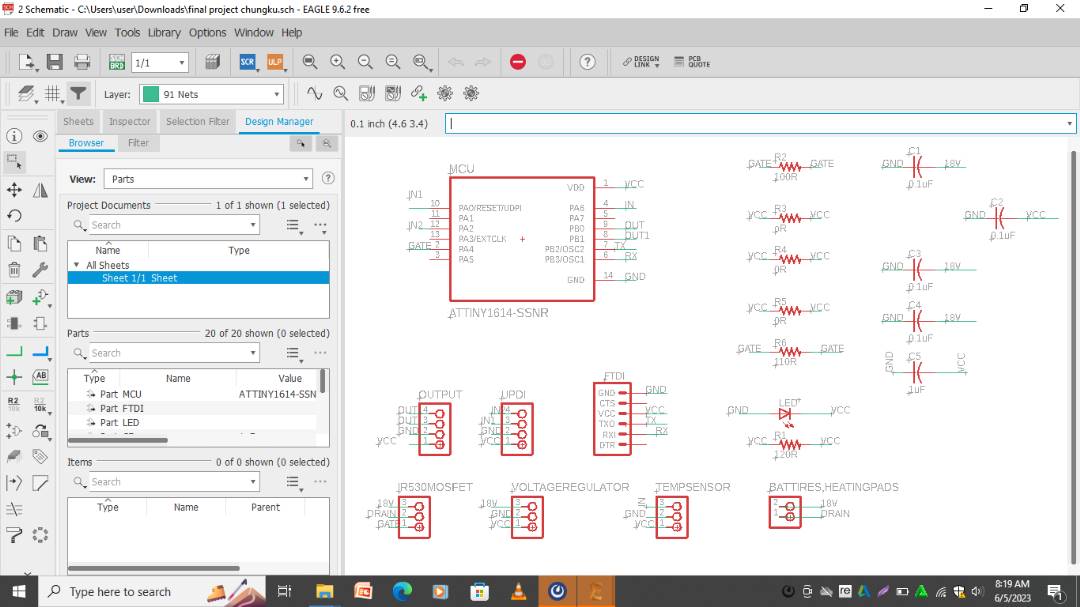
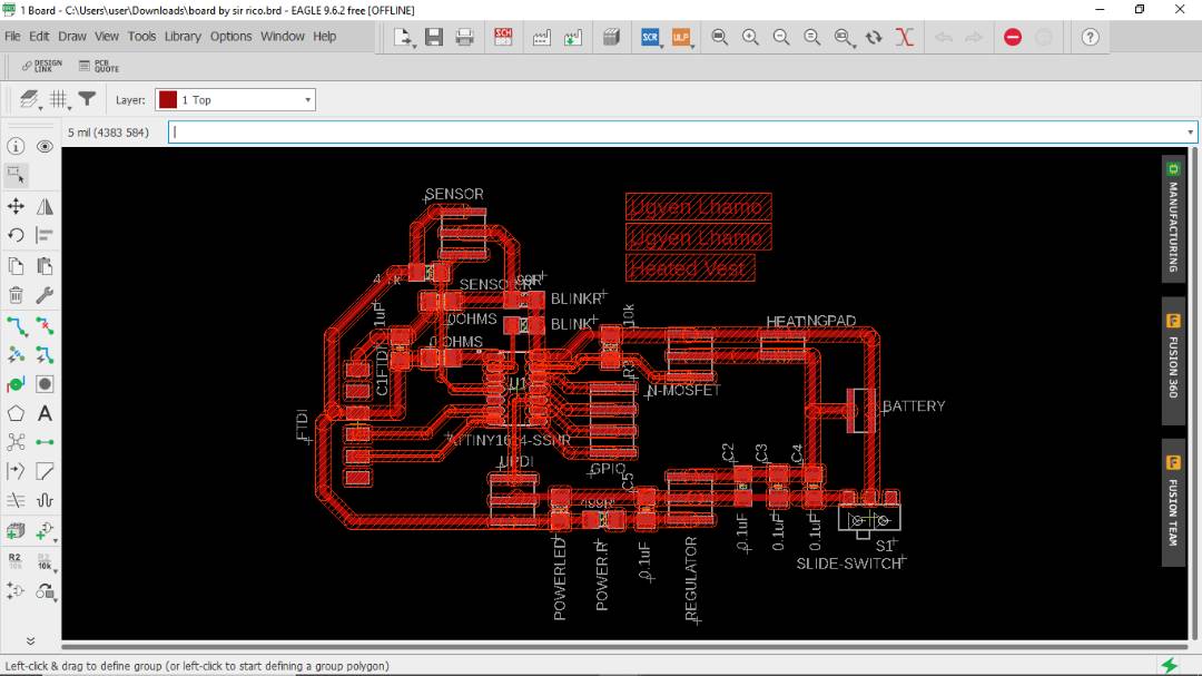
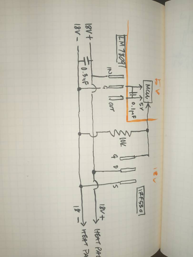
SO without wasting anytime we had to schedule our time and plan what we were supposed to do during the 2 weeks boot camp. So i designed my final project board after doing research and study on voltage regulator, below here is the schematic and board design that i did on eagle. I took one night to design my board and the ext day my work was to mill the board and solder it.
The most important part of electronics was that we have to know and memorize our board in our mind, Like which pin goes to what pin and which is GND and which is VCC. I memorized my board by drawing it first and then understanding the connection like i did in the image below, This was our Guru Rico's idea since we had to again look at the board design on eagle so it was wasting our time. when we do this we can easily know which pin goes to what and which line is GND, VCC and signal pin.

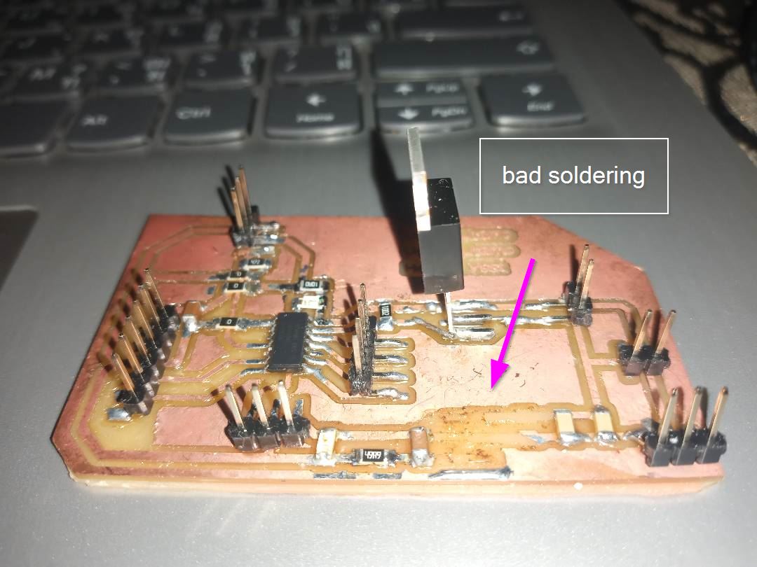
After done with soldering this was the board i milled my first board. I have milled like 6 to 7 boards and i know where all the components are kept lol. However i never gave up on it. I milled my board again and again, find out mistake and again milled the board and then again debugged.Below here is the image where my soldering was very bad were my voltage regulator came out while working on it.
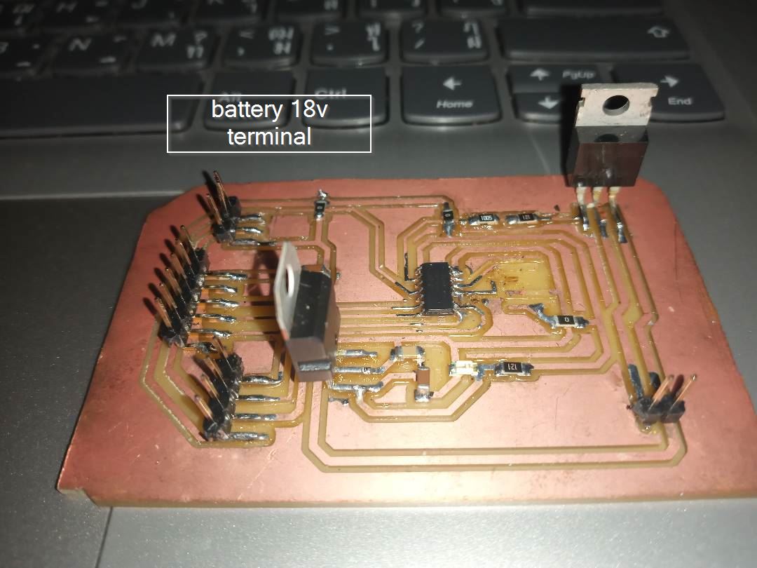
Here In my board i find out that for the 18v battery supply i needed a terminal where i again redesigned my board and added 2 header pin so when i supply 18 volt from t he batteries to the board the voltage regulator will regulate the volt and supply 5 volt for the MCU and rest will be going to the heating pads through the triggering of the sensor and through the mosfet gate and then the heating pads. for the whole system to turned off i used a switch button to turn off and on when needed.
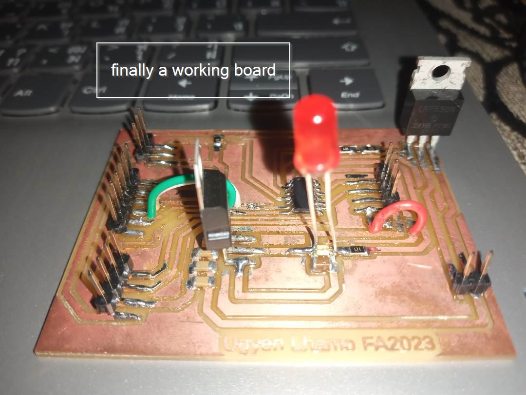
Here was a working board finally after lots of struggle, soldering milling and re designing i tried blink LED on the board and it worked out well.As you can see in the video below where the LED is blink and even showing in the serial monitor which shows that finally i have a working board.YES!
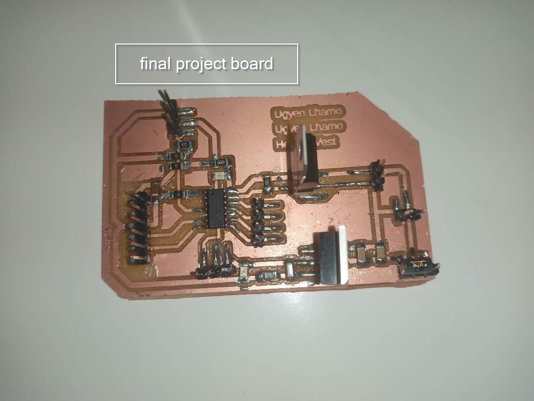
Finally this is my working board for final project. So this was my last milling of the board, i soldered and then the final hero shot of my board.
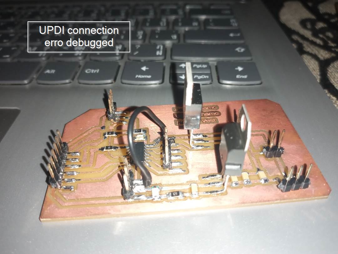
Since out of all 6 of us my project was bit complicated since i had to deal with 18 volt so it was very difficult since i had to mill my board for 5th times. But for me i always think we learn things from mistake so didn't give up (Got the inspiration from Rico),Below here is an image Where i plugged in 9v to see how much volt is the regulator can pass to the mcu and the heat pads and the result was not good since the regulator was only giving 2volt to the MCU which was not a good sign, actually the MCU needs 5v and the heat pads needs more then 9v so this was very confusing to me. after few hours of research me and Rico we checked a data sheet on internet and found out that the mosfet was wrong we had to change the regulator which gave 5v output so the right regulator wasLM7806 instead of LM7809
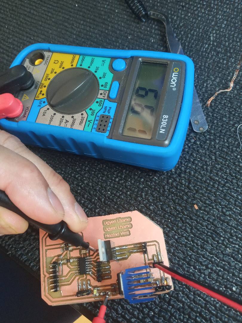
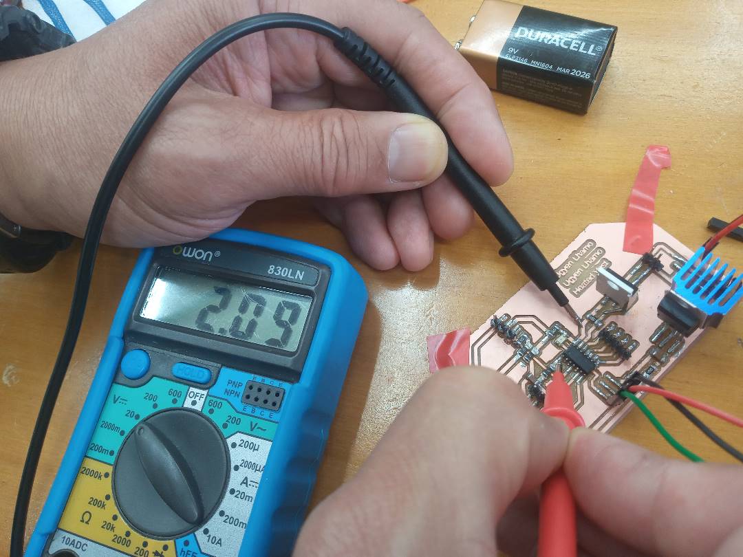
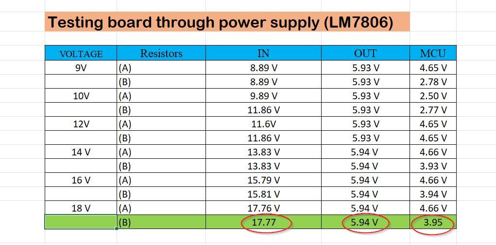
Giving 18volt directly to you board can destroy your whole board and the Micro controller so firstly we need to study the diagram how the current flows and how much the current flows through the regulator to the mcu adn to the heat-pads. i checked out giving volt from the power supply to the mcu. by gradyally increasing the volt from 9 till 18 to see the result.We even had to calculate the resistor since resistor was playing a great role in distributing the voltage.
Below here is the calculation for resistors that i used in my board for the voltage regulator i tested two resistor and given name Resistor A and Resistor B.
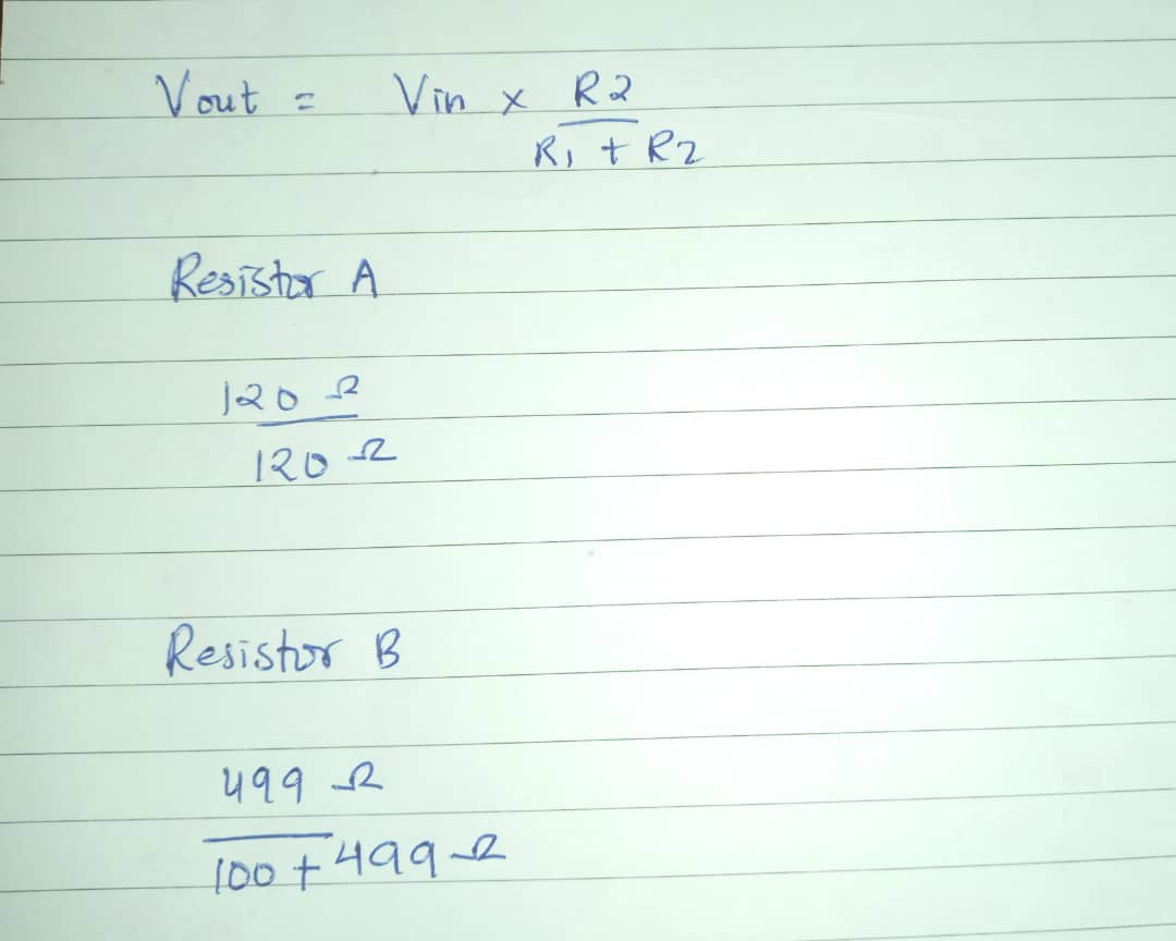
I gave the power supply to the board starting from 9 volts till 18 volts and these are the results.At the end Resistor B was the correct resistor that could load 18v and supply 17 volt to the heatpad which comes from the in put pin of the regulator and 5.94 volt to the MCU
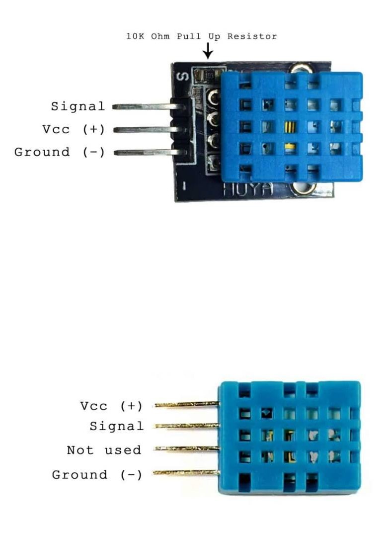
This week is networking and communication week. but my heating pads were taking so long to arrive so i thought of making my own heating pad and tried checking the temperature using the temperature and humidity sensor. I made a heating pad using Nichrome wire, batteries and a foam.
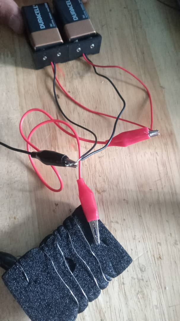
Below here is the video where i tried heating pads and sensor and the serial monitor and i even tried on my board.This is the pinout diagram of the sensor that i used for checking if my heating pads works or not.This is the code for DHT11 temperature sensor. At first i tired using an ordinary wire but the batteries got heated up instead of the wire so I watched some youtube tutorial and found out that the wires were not normal wire that we get from the lab so i went to a hardware shop and bought nichrome wire. After that i use an adapter since the batteries in the lab was just 9 volt and i thought of adding two batteries which could make up 18 v and the heat was quiet in good amount. So after trying with the double batteries i found out that i could finally make a heating pads just using a nichrome wire two batteries and a simple foam. After that i checked on serial monitor using the DHT11 temperature sensor and finally it was a success for me. I was quiet happy since the heating pads were not getting delivered and my final project was all depended on the heating pads and the problem got solved. The serial monitor shows the increase in temperature from the heating pads which shows that my heating pads are finally working.
     #include <SimpleDHT.h>
     int pinDHT11 = 4;
     SimpleDHT11 dht11(pinDHT11);

     void setup() {

       Serial.begin(9600);
       Serial.println("Temperature and Humidity data");
     }

     void loop() {
       Serial.println("Temp test for heater jacket");
       Serial.println("==========================");
       // read without samples.
       byte temperature = 0;
       byte humidity = 0;
       int err = SimpleDHTErrSuccess;
       if ((err = dht11.read(&temperature, &humidity, NULL)) != SimpleDHTErrSuccess) {
         Serial.print("Read DHT11 failed, err="); Serial.print(SimpleDHTErrCode(err));
         Serial.print(","); Serial.println(SimpleDHTErrDuration(err)); delay(1000);
         return;
       }

       Serial.print((int)temperature); Serial.print(" *C, ");
       Serial.print((int)humidity); Serial.println(" H");

       delay(1500);
     }